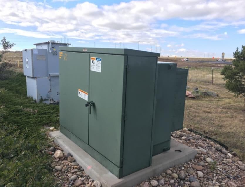
Power-quality correction for the whole facility.
The MPTS Power Management Controls System installs in parallel with your main distribution. It measures continuously and adjusts its correction as the load changes, across the facility rather than one panel at a time.
How it works
MPTS continuously measures voltage, current, kW, kVA, kVAR, power factor and harmonic distortion, then applies dynamic parallel RLC correction. It logs data with the system off and on, so its effect can be shown under your real operating conditions.
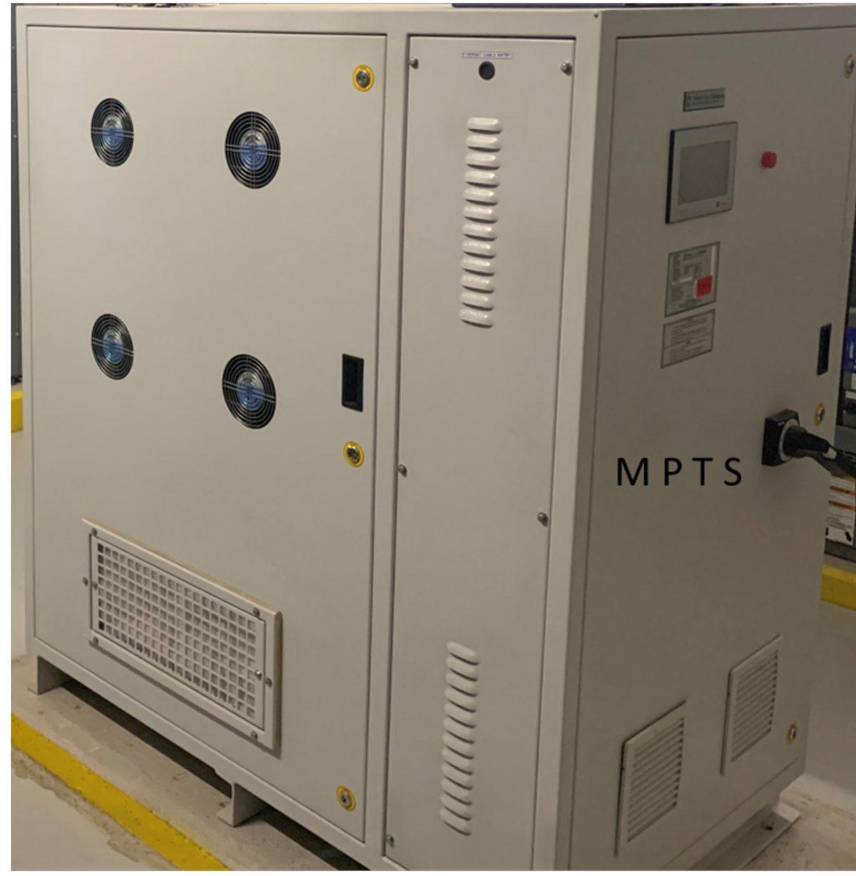
Where the name comes from
MPTS stands for Maximum Power Transfer Solution, after the maximum power transfer theorem of 1840, now known as Jacobi’s law, which describes how a source delivers the most power when its impedance and the load’s are matched. Trans Power Company calls the product a Power Management Controls System, and the two names are used together.
Models
| Attribute | H240 | H490 |
|---|---|---|
| Service size | Up to 1,000 A | Up to 2,000 A |
| Reactive capacity | 200 kVAR | 400 kVAR |
| Cabinet size | 32 × 43 × 56 in | 35 × 63 × 63 in |
Standard units, not built to order, so deployment is straightforward. Several units can share one electrical network, and the two models can be mixed to match the load.
As stated by Trans Power Company
- Power factor corrected up to 0.98
- Maintenance-free for 10 years or more
- UL and CSA certified; installed to the National Electrical Code and local codes
- Works with existing and new equipment: utility transformers, main panels, generators, solar and battery systems
- Categorized as an all-in-one power management solution by UL and the US Patent Office
- Not a parasitic load: it does not burden the electrical network it corrects
- Remote monitoring, data logging and reports, with BACnet integration for building controls
- Performance measured before and after on every project, following the DOE’s IPMVP Option B guideline
What MPTS is not
One unit per circuit, in parallel with the load.
A typical layout from Trans Power Company: the utility transformer feeds the main switchgear, and each large feeder gets its own MPTS unit connected in parallel, ahead of the loads it serves. Each unit corrects its own circuit, so losses fall on every feeder and the power factor at each one is held near 0.97.
Swipe the drawing sideways to see all of it.
What the facility gets, and what the meter shows.
Trans Power Company’s own summary of MPTS, in two columns: the operating outcomes a facility cares about, and the electrical quantities it measures to prove them.
For the facility
Lower operating and maintenance cost
Less service, repair and replacement expense.
Less downtime and fewer equipment failures
Better reliability of the connected equipment.
Longer equipment life
Less electrical stress and premature aging.
Released electrical capacity
Room for more load on the same panels and transformers.
Lower demand and energy use
Lower electrical operating cost.
On the meter
- Lower: Current (A)
- Lower: Apparent power (kVA)
- Lower: Reactive power (kVAR)
- Lower: Peak demand (kW)
- Lower: Harmonic distortion (THDi, THDv)
- Lower: I²R losses and electrical stress
- Higher: Power factor
- Higher: Available capacity
Measures · Manages · Corrects · Saves
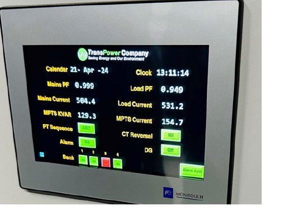
Savings and payback, as stated by Trans Power Company
- $30,000+
- Annual operating-cost savings per unit
- 1–3 years
- Typical payback
- 0.98–0.99
- Power factor reached
These are the developer’s figures, not ours, and its own material notes that savings and payback vary with the facility’s load profile, utility rates, operating hours and installed configuration. The monitoring meter below is how we find out what they would be at your site.
Sized from your own load data.
Monitoring meter
A power-monitoring meter goes in at your service: $5,000, credited toward the system if you go ahead.
Load analysis
The data sizes the system: which model, how many units, and where they connect.
Installation
Your electrician installs MPTS in parallel with the main distribution, and the meter keeps recording.
Where MPTS is installed
Trans Power Company lists installations at a military command center, federal office and courthouse buildings, a product-safety testing laboratory, hospitals and a nursing home, school districts and a university, banks, county and city government buildings, an aluminum extrusion plant, a chemical plant, a printing press, a museum, a commercial greenhouse and a metalworks overseas. We do not name customers; ask and we will put you in touch with references.
Recover capacity on transformers and feeders.
Distribution transformers and feeders are rated in kVA. Where reactive and harmonic current fills part of that rating, correcting it at the customer’s service can free capacity for new load and help defer upgrades. We propose measured field demonstrations: an agreed measurement boundary, a baseline, then MPTS-off and MPTS-on periods judged on independently measured kVA, kVAR, current, power factor and harmonics.